Integrating UAV-based Lidar and Photogrammetry
Dense 3D Point Cloud Generation with Ultra-high Precision
A UAV project in Germany has integrated photogrammetric bundle block adjustment with direct georeferencing of Lidar point clouds to considerably improve the respective accuracy.
最近的无人机(无人机或“无人机”)平台共同收集图像和激光雷达数据。他们的合并评估可能会以某些毫米的精度和分辨率生成3D点云,迄今为止仅限于陆地数据捕获。本文概述了一个项目,该项目将摄影测量束块调整与激光点云的直接地理发作,以通过数量级提高各自的准确性。在高精度密集的3D点云的产生过程中,将LIDAR范围测量添加到多视图 - 敏感性(MVS)图像匹配中,组合处理的进一步好处。
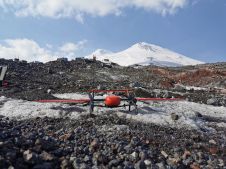
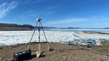
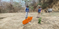
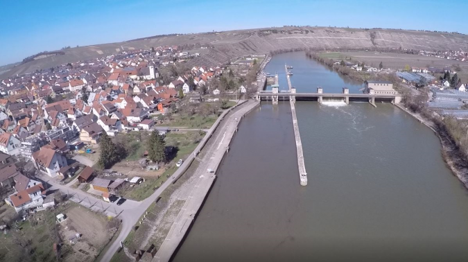
The project was aimed at the area-covering monitoring of potential subsidence of about 10 mm/year by a repeated collection of very accurate and dense 3D point clouds. The considerable size of the test site in Hessigheim, Germany, prevents terrestrial data capture. As visible in Figure 1, the site consists of built-up areas, regions of agricultural use and a ship lock as the structure of special interest.
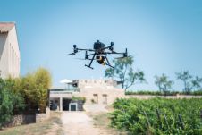
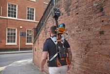
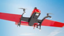
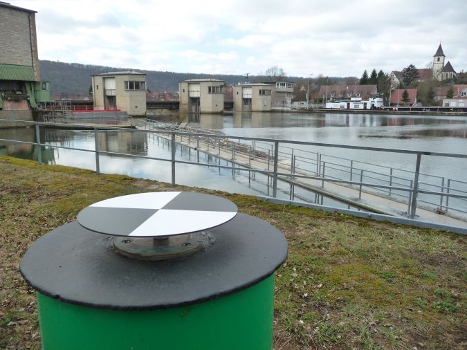
传统的监控,network of several pillars was established in the vicinity of the lock. As depicted in Figure 2, photogrammetric targets signalized the pillars to make them available as check and control points for georeferencing. For UAV data collection, aRIEGL RiCopteroctocopter was used equipped with a RIEGLVUX-1LRLidar sensor and two Sony Alpha 6000 oblique cameras. With a nominal flying altitude of 50m above ground level, a strip distance of 35m and a scanner field of view (FoV) of 70°, the system captured 300-400 points/m² per strip and 800 points/m² for the entire flight block due to the nominal side overlap of 50%. The flight mission parameters resulted in a laser footprint diameter on the ground of less than 3cm with a point distance of 5cm. The ranging noise of the scanner is 5mm. The trajectory of the platform was measured by an APX-20 UAV GNSS/IMU system to enable direct georeferencing. The two Sony Alpha 6000 oblique cameras mounted on the RiCopter platform have a FoV of 74° each. Mounted at a sideways-looking angle of ±35°, they captured imagery at a ground sampling distance (GSD) of 1.5-3cm with 24 megapixels each.
Lidar Strip Adjustment and Automatic Aerial Triangulation
After direct georeferencing, a typical Lidar workflow includes a strip adjustment to minimize differences between overlapping strips. This step improves georeferencing by estimating the scanner’s mounting calibration as well as correction parameters for the GNSS/IMU trajectory solution. Typically, a constant offset (Δx, Δy, Δz, Δroll, Δpitch, Δyaw) is estimated for each strip. Alternatively, time-dependent corrections for each of these six parameters can be modelled by splines.
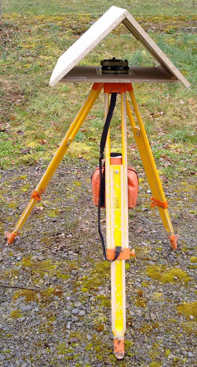
Figure 3 exemplarily depicts a Lidar ground control plane used for absolute georeferencing. Each signal features two roof-like oriented planes at a size of 40cm × 80cm with known position and orientation. The evaluation of this project’s Lidar strip adjustment additionally applies the signallized pillars depicted in Figure 2. These photogrammetric targets provide elevation differences to the georeferenced point cloud at 33 targets. In the investigations, these differences resulted in an RMS accuracy of 5.2cm. To enable georeferencing of the Sony Alpha oblique image block by automatic aerial triangulation (AAT), six of the photogrammetric targets were selected as ground control points (GCPs). The remaining 27 targets provided differences at independent check points (CPs) ranging between 5.2cm (max.) and 1.2cm (min.) with an RMS of 2.5cm.
因此,在对不同传感器数据的独立评估期间,LIDAR带的调节和束块调节都无法产生所需的3D对象点精度。然而,如果通过所谓的混合地理发酵来整合这两个步骤,准确性将显着提高(Glira 2019)。
机载激光雷达和成像的混合运用y
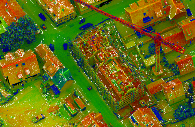
Figure 4 depicts a section of the project’s Lidar points, colour-coded by the intensity value. The overlaid white points represent tie points from the bundle block adjustment of the Sony Alpha imagery. Usually, this step estimates the respective camera parameters from corresponding pixel coordinates of overlapping images. The object coordinates of these tie points are just a by-product.
In contrast, hybrid georeferencing applies these tie point coordinates to minimize their differences to the corresponding Lidar points. This process estimates time-dependent corrections of the flight trajectory similar to traditional Lidar strip adjustment. Within this step, tie point coordinates add geometric constraints from AAT. This provides considerable constraints from the image block to correct the Lidar scan geometry. This is especially helpful if both sensors are flown on the same platform and thus share the same trajectory. Hybrid georeferencing additionally opens up information on ground control points used during bundle block adjustment. Thus, georeferencing of Lidar data no longer requires dedicated Lidar control planes. Instead, all the required check point and control point information is available from the standard photogrammetric targets, which is of high practical relevance.
The authors applied a flexible spline as a powerful model for trajectory correction. This flexibility can potentially result in systematic deformations if applied during standard strip adjustment. In contrast, integrating information from stable 2D image frames as oriented during bundle block adjustment reliably avoids such negative effects. Figure 5 depicts the result of the hybrid approach from the OPALS software used. The six GCPs marked by the red circles and the remaining 27 targets used as CPs coincide with the AAT already discussed. For hybrid georeferencing, the elevation differences are -1.5cm minimum, 0.7cm maximum and -0.4cm mean. The corresponding standard deviation of 0.6cm clearly indicates that sub-centimetre accuracy is now feasible.
Combined Point Clouds from Lidar and Multi-view Stereo
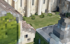
如图4所示的摄影测量点只是束块调整的副产品,因为MV在随后的步骤中提供了密集的3D点云。原则上,MVS点云的几何精度直接对应于GSD,因此对应于各个图像的规模。即使在适当的图像分辨率下,这也允许3D数据捕获。但是,立体声映像匹配可以推测至少两个图像中对象点的可见性。对于非常复杂的3D结构来说,这可能是一个问题。相反,每当物体外观从不同位置看到时,LIDAR传感器的极性测量原理都会有利。对于植被或起重机棒等半透明物体(如车辆和行人),或在非常狭窄的Urban Canyons以及建筑工地中,这是正确的(见图4)。LiDAR的另一个优点是测量反射信号的多个反应,从而使植被穿透。另一方面,将图像纹理添加到LiDar Point云中对于可视化和解释都是有利的。结合MV的高分辨率能力,这支持了在3D点云生成期间正确整合LiDAR和MVS的论点。
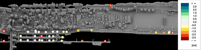
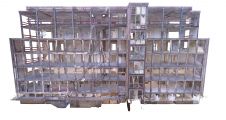
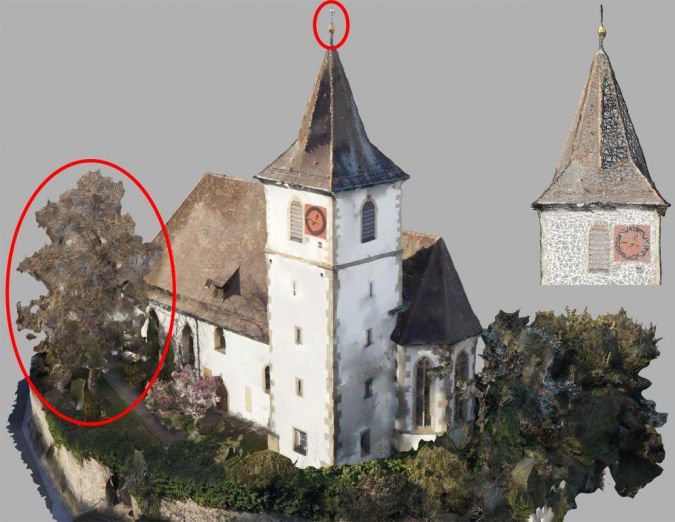
Figure 6 shows a 3D textured mesh generated from the Sony Alpha images by the MVS pipeline realized in theSURE softwarefromNframes. As can be seen in Figure 7, much more geometric detail is available, e.g. on the top of the church and in vegetation after Lidar data is integrated. Face count typically adapts to the geometric complexity, which is also visible for the small section of the church tower. As an example, Figure 6 consists of approximately 325,000 faces, while Figure 7 features 372,000 triangles.
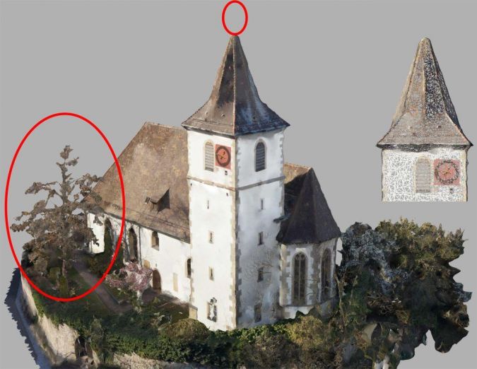
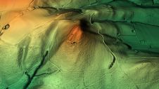
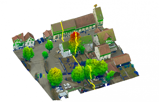
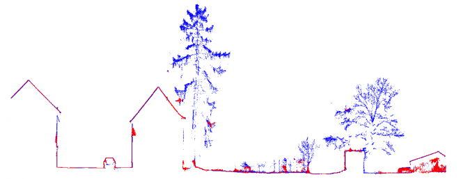
图8和9证明了在测试位点的另一部分,LIDAR和MVS的互补特性为3D点。图8描述了MVS产生的RGB色点;根据各自的海拔,对LIDAR数据叠加的数据是颜色编码的。最后,黄线表示用于提取图9中所示的点的轮廓。在树上,点云与MVS(红色)和激光雷达(蓝色)之间的差异尤为明显单激光射线路径。
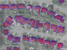
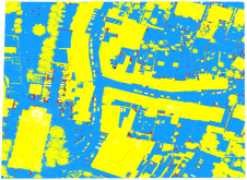
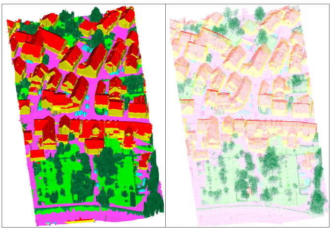
Whereas point clouds as shown in Figures 8 and 9 are an unordered set of points, meshes as depicted in Figures 6 and 7 are graphs consisting of vertices, edges and faces that provide explicit adjacency information. The main differences between meshes and point clouds are the availability of high-resolution texture and the reduced number of entities. This is especially useful for subsequent automatic interpretation. Generally, many (Lidar) points can be associated with a face. The authors utilized this many-to-one relationship to enhance faces with median Lidar features derived from the respective associated points. This enabled them to integrate inherent information from both sensors in the mesh representation in order to achieve the best possible semantic segmentation. Figure 10 shows the labelled mesh as predicted by a PointNet++ classifier (left) and the labels transferred to the dense Lidar point cloud (right), subsampled by factor 20 for visualization. The following class colour code is used: facade (yellow), roof (red), impervious surface (magenta), green space (light green), mid and high vegetation (dark green), vehicle (cyan), chimney/antenna (orange) and clutter (gray).
The forwarding was accomplished easily by re-using the many-to-one relationship between Lidar points and faces. Thereby, the semantic segmentation of the Lidar point cloud uses features that have originally only been available for the mesh, e.g. texture. Hence, the semantic mesh segmentation uses inherent features from both representations, which is another benefit of joint image and Lidar processing.
Conclusion
This article presents a workflow for hybrid georeferencing, enhancement and classification of ultra-high-resolution UAV Lidar and image point clouds. Compared to a separate evaluation, the hybrid orientation improves accuracies from 5cm to less than 1cm. Furthermore, Lidar control planes become obsolete, thus considerably reducing the effort for providing control information on the ground. The authors expect a further improvement by replacing the current cameras mounted on the RIEGL RiCopter with a high-quality Phase One iXM system to acquire imagery of better radiometry at higher resolution. This will further support the generation and analysis of high-quality point clouds and thus enable UAV-based data capture for very challenging applications.
确认
介绍的研究的一部分是在科布伦兹的德国联邦水文学研究所(BFG)授予的项目中资助的。感谢Gottfried Mandlburger,Wilfried Karel(Tu Wien)和Philipp Glira(AIT)在混合地理生产期间对蛋白石软件的支持和改编。在联合工作期间,Tobias Hauck的支持也得到确定。
Make your inbox more interesting.Add some geo.
Keep abreast of news, developments and technological advancement in the geomatics industry.
Sign up for free